Elevator Mechanism
An elevator is a common FRC mechanism which allows the robot to reach different scoring heights. Robots must fit into specific dimensions before matches start, and an elevator is a compact way to fit into the restrictions while allowing extension once the match begins. This becomes crucial in games involving elevating game pieces, moving mechanisms above field elements, or even raising up the entire robot. This project was a mimic CAD of the elevator my team used in order to better understand how it works.
How it Works
There are multiple types of FRC elevators, including chain and pulley, rack and pinion, and continuous—the elevator I did was a chain and pulley. This type of elevator is an all rounder; it’s relatively light, not super complex to assemble, and can reach high enough to be suitable for many game challenges, which is why I wanted to CAD it.
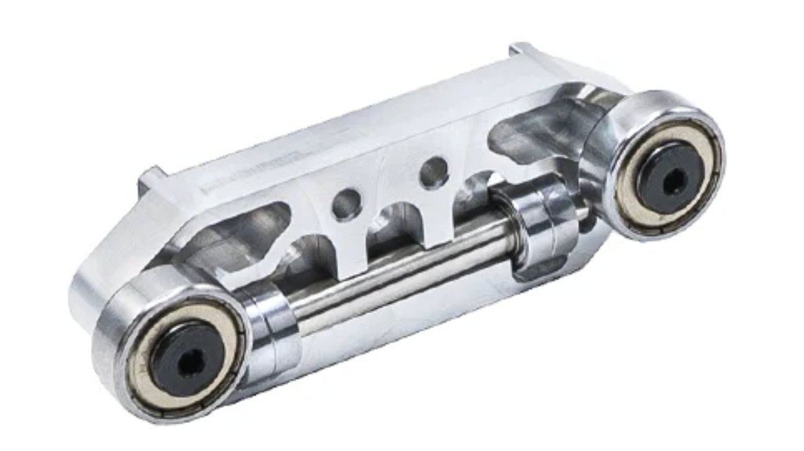
The frame of the elevator consists of a pair of inner and outer box beams. The inner box beams are what move up and down; the carriage. Between the box beams is a bearing block which allows for smooth sliding movement along the outer beam and prevents the elevator from dislodging or twisting when it’s extended.
Pulleys are attached at the bottom and top of the mechanism with a chain pulled around them. Since elevators need to lift a very large load, a reduction (ratio 10 or 12:1) is applied through a gearbox next to the bottom pulley. The pulley is on the same axle as the last gear of the gearbox, allowing for higher torque to be applied.
The carriage is then attached to the chain, so when the motor spins the movement of the chain carries the elevator up and down.
Design Constraints
In addition to minimizing weight, an elevator design requires careful attention to the alignment of the chain to prevent uneven loading and must resist binding or twisting when extended. More stages means a heavier load to lift as well as a more complex rigging, which is why we used a 2 stage elevator which is easier to keep aligned and more simple to rig and adjust. Another way to reduce weight is to window the box beams; this not only lowers the weight of the structure but it also provides support with the triangular pattern.
Design Process
While the individual components of an elevator aren’t very complex, the assembly is what can become difficult.
To design this, I first created the main parts and then began creating parts as I assembled.
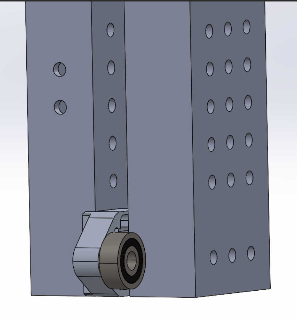
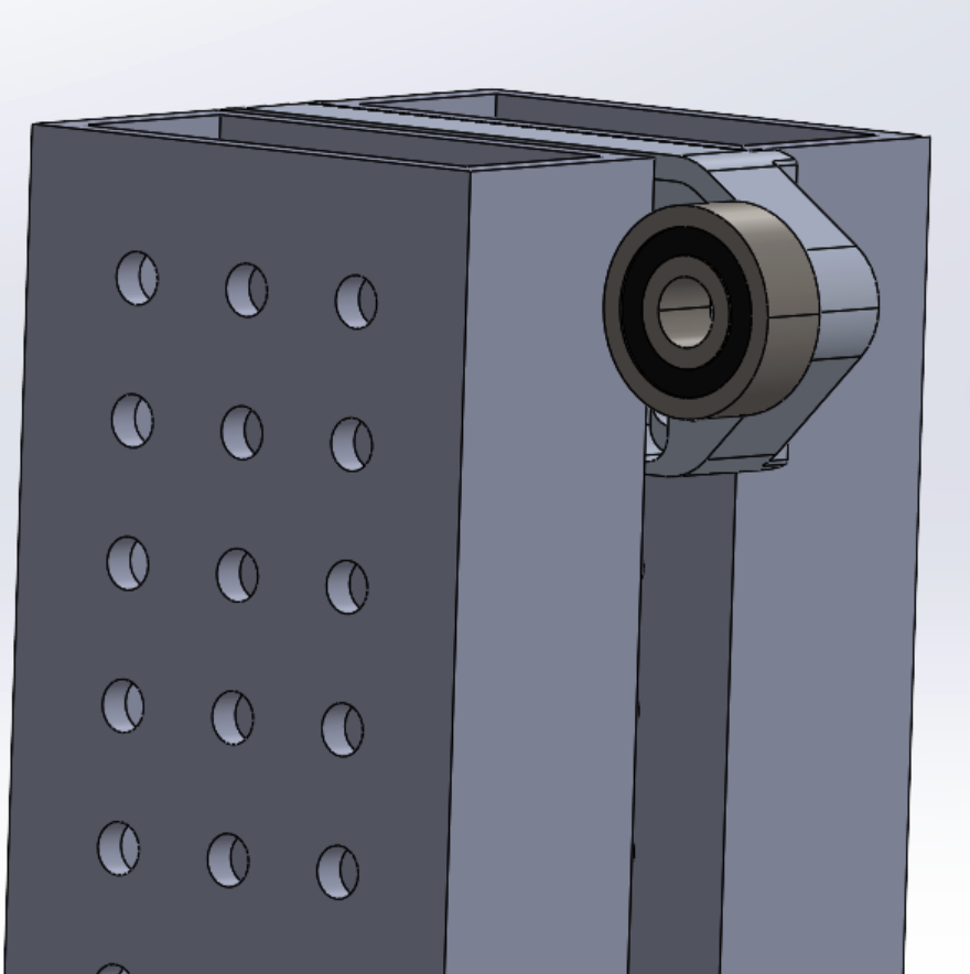
First, a bearing block is attached to the bottom of the carriage, and another is attached to the top of the outer box beam. The bottom bearing block moves up and down with the carriage, while the one on the top remains stationary and provides support.
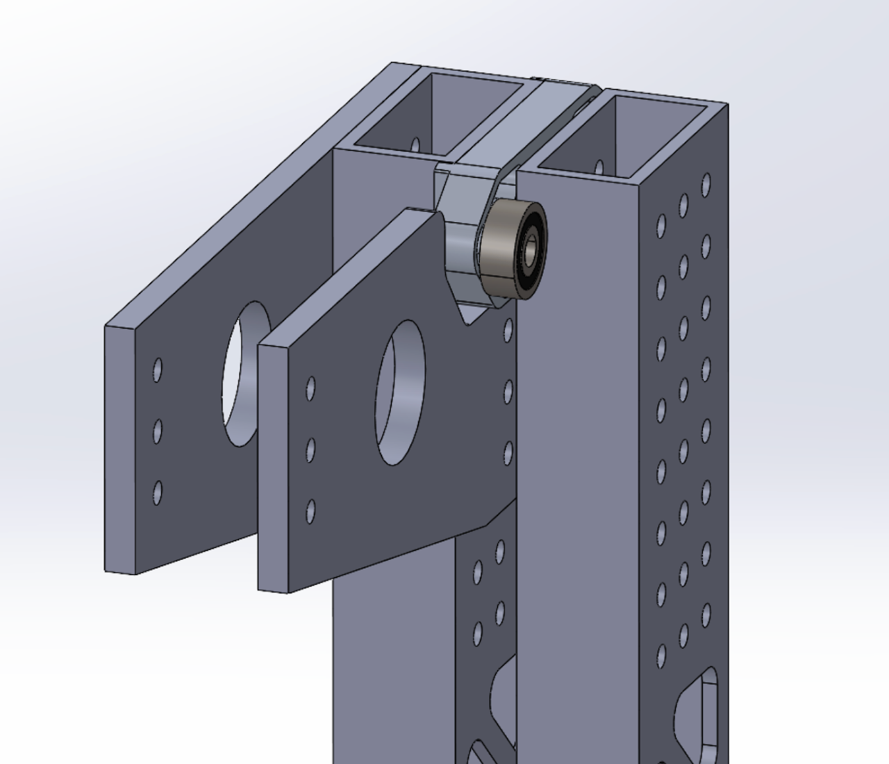
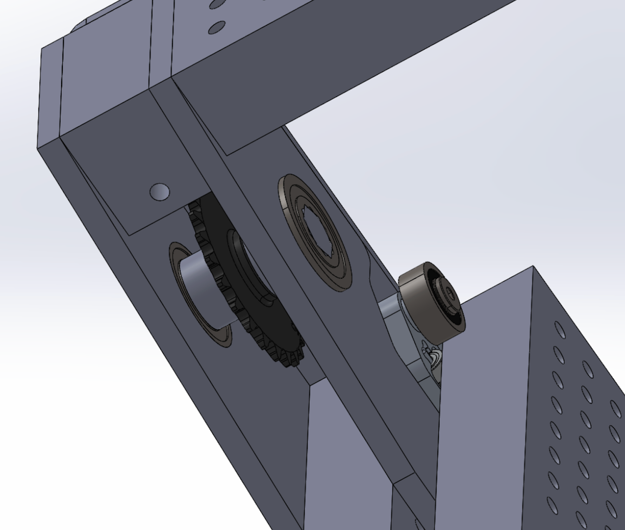
Next, I attached the plates to support the top pulleys.
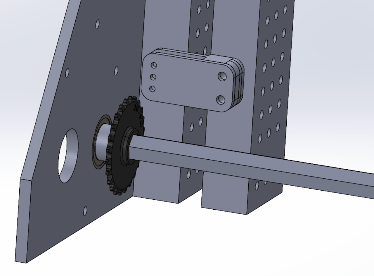
For the bottom pulley, there’s a mounting plate that is attached to the drivetrain as well as the outer box beams. An axle spans across the entire elevator and the bearings for it are on the mounting plate. Both the bottom pulleys are on this axle in order to keep both sides connected and aligned, and there are spacers to ensure the pulleys are vertically constrained and the chain won’t be at an angle. I also attached the chain clamps to the carriage. These are super important because they’re what allows the carriage to move up as the chain moves.
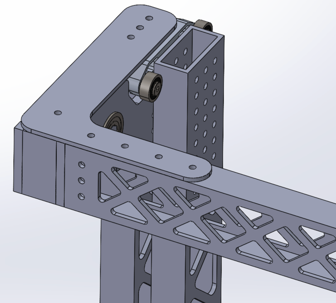
I then used flat L plates to attach a box beam which would mount a limelight.
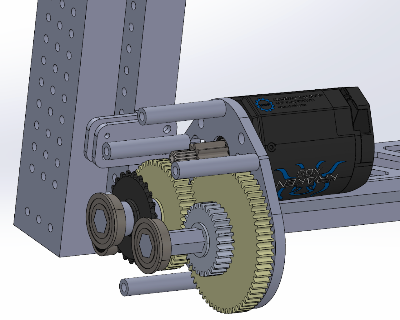
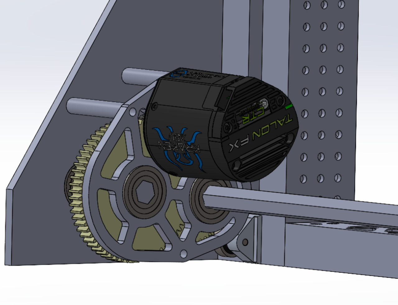
Lastly, for an elevator which needs to lift a large weight, a high gear ratio (around 10 or 12 to 1) is necessary. Thus, I designed a 2 stage gearbox (first stage 8:1, second stage approximately 1.5:1). The last gear in this assembly would be on the same axle as the pulley, transferring the reduction to the chain-pulley mechanism.
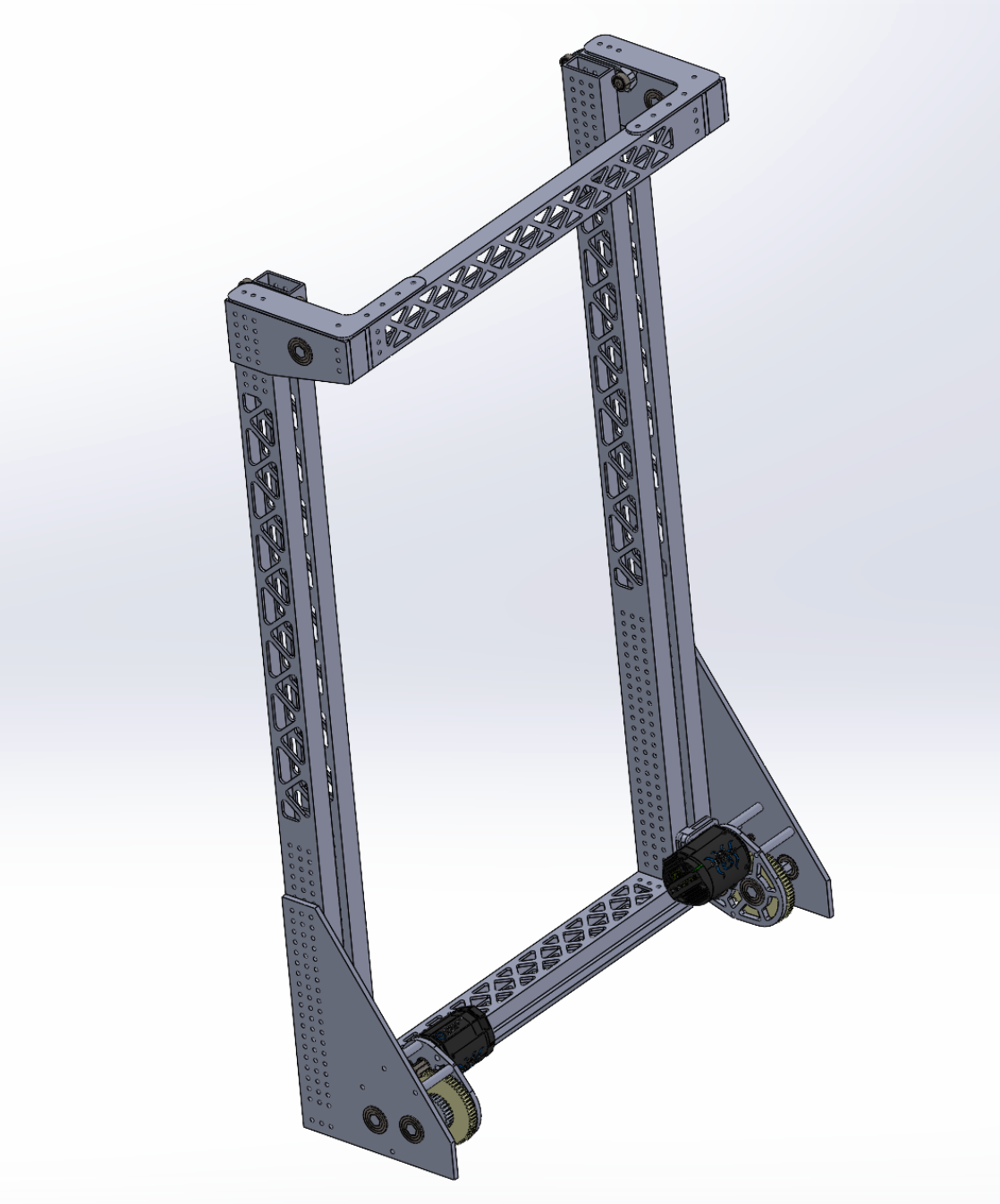
I followed the same process as when I did my first gearbox project, but I included the windowed plate. The other end of this gearbox is the mounting plate, so I only needed to make one plate. However, since there needed to be a gearbox on each side (to apply reduction on both sides) I needed to do the gearbox assembly separately for each one, which proved to be rather tedious.
However, once that was completed the elevator was officially complete!
Challenges
A large challenge I faced during this project was getting every component to line up. Bearing holes and mounting holes didn’t align, there were collisions on multiple occasions, and I had to continuously adjust dimensions. This taught me why a power sketch is so important; using one can avoid many of these issues because every component is already lined up, while I instead made my parts separately and had no way of seeing them together until I assembled them.
Reflection
Overall, I really enjoyed this project as I had struggled previously to understand how a chain and pulley elevator works. If I were to do this again or any other project for that matter, I’d definitely start with a power sketch. This project taught me the consequences of not using one, and I now see why it’s so crucial.
Creating each part and assembling them in CAD myself was a great hands-on experience and I can confidently explain the how and why of this kind of elevator.
Glossary
- Box beam: A hollow rectangular prism with edges of ⅛ or 1/16 thickness—commonly used in FRC
- Carriage: Moving assembly of an elevator
- Reduction: Gear ratio which increases torque in exchange for speed, allowing more force to be applied
- Limelight: FRC component which is crucial for the robot to detect objects and recognize its position on the field