Flip-Up Intake Mechanism
Summer 2026 · Team robot mechanism
Project Overview
An intake is a critical mechanism on an FRC robot, responsible for collecting game pieces and transferring them into the robot for further manipulation. During the 2026 FRC season, the game required robots to rapidly collect large quantities of balls and feed them into an internal hopper for shooting.
Our team's original robot used a linear-slide intake, driven by a rack-and-pinion mechanism to extend and retract the intake assembly. Although functional, the design experienced significant reliability issues throughout the competition season. The linear slides frequently vibrated and became unstable during operation, and on several occasions, the entire intake assembly detached from the robot.
These failures highlighted the need for a more mechanically stable, reliable, and robust intake mechanism that could withstand the demands of competition while maintaining efficient game-piece collection.
During the offseason, I volunteered to design an alternative intake mechanism. Inspired by Team 1778's 2025 flip-up intake design, I decided to explore a pivot-based mechanism that rotates to deploy and retract the intake, rather than relying on linear slides. The goal was to eliminate the instability associated with the original sliding mechanism while developing a more reliable and mechanically robust alternative.
This project documents my engineering process, including design requirements, mechanical considerations, CAD development, prototyping, challenges encountered, and lessons learned.
Mechanism Overview
Flip-Up Mechanism
A flip-up intake works by using a powered pivot to move a set of rollers. All components of the robot must start inside the frame perimeter, and a flip-up mechanism allows for fast and efficient extension beyond the frame perimeter during operation.
Power Transmission and Roller Operation
A gearbox reduction increases torque and drives a sprocket, which is connected by a chain to a larger sprocket. This larger sprocket is directly attached to the intake plates, meaning that when the gearbox rotates, it moves the entire intake assembly along with it.
Additional motors are mounted on the moving portion of the intake to power the rollers, which collect balls and feed them into the robot's hopper.
Hopper Integration
A hopper is also a crucial part of the intake system, as it provides additional space for storing balls before they are shot out.
In my design, when the roller plates move downward, they push the hopper plates along with them, allowing the hopper to expand as the intake deploys. A net mounted above the hopper further increases its storage capacity, allowing even more balls to be collected before shooting.
Design Constraints
This project involved several design constraints that needed to be considered when developing the mechanism.
1. Gearbox Size and Reduction Ratio
The gearbox must be compact but also provide enough gear reduction to successfully lift the intake. We decided to use a lightweight material for the plates in order to limit weight, but the mechanism still requires a large reduction.
I tried to keep the reduction ratio as large as possible while keeping the gearbox above the drivetrain box beam (with inspiration taken from Team 1778’s 2025 flip-up intake).
My final reduction ratio was approximately 36:1. I selected this ratio based on the available gear combinations, aiming for a reduction greater than 30:1 while ensuring the gearbox remained above the drivetrain box beam.
2. Chain Tensioning and Clearance
A tensioner is used to keep the chain between the sprockets tight. If the chain becomes slack, skipping could occur and greatly affect the intake’s performance.
I used a turnbuckle, but there needs to be enough space to ensure the turnbuckle doesn’t interfere with surrounding components. Obstructions include anything on either side as well as the sprockets themselves.
Thus, I had to calculate the angle through which the intake would move and then calculate how far the chain would move, ensuring that the turnbuckle had adequate clearance throughout the intake's range of motion.
Since the intake rotates approximately 90 degrees, I used the arc length of the driven sprocket to estimate how far the chain and turnbuckle would travel. I then compared this distance, along with the turnbuckle's length, against the available space between the sprockets to make sure it wouldn't collide with either sprocket during deployment.
3. Game-Piece Compression
Compression is the amount that either the game piece or rollers compress when intaking. If compression is too little or too high, the balls may not be collected efficiently or they can get stuck in the rollers.
In CAD, compression is accounted for by the distance between the rollers that will interact with the game piece.
I researched online about compression and talked to my team about it so we could determine an appropriate amount of compression for the mechanism.
4. Extension and Height Restrictions
FRC has strict regulations on how far a mechanism can extend horizontally and vertically.
I had to ensure that every part of the intake was within the 12-inch extension limit beyond the frame’s perimeter, so I had to account for that when considering compression.
Additionally, our team wanted to fit underneath the trench, which was 22 inches off the ground, so I also had to make sure the mechanism remained below this height restriction.
Design Process
1. Initial Gearbox and Intake Design
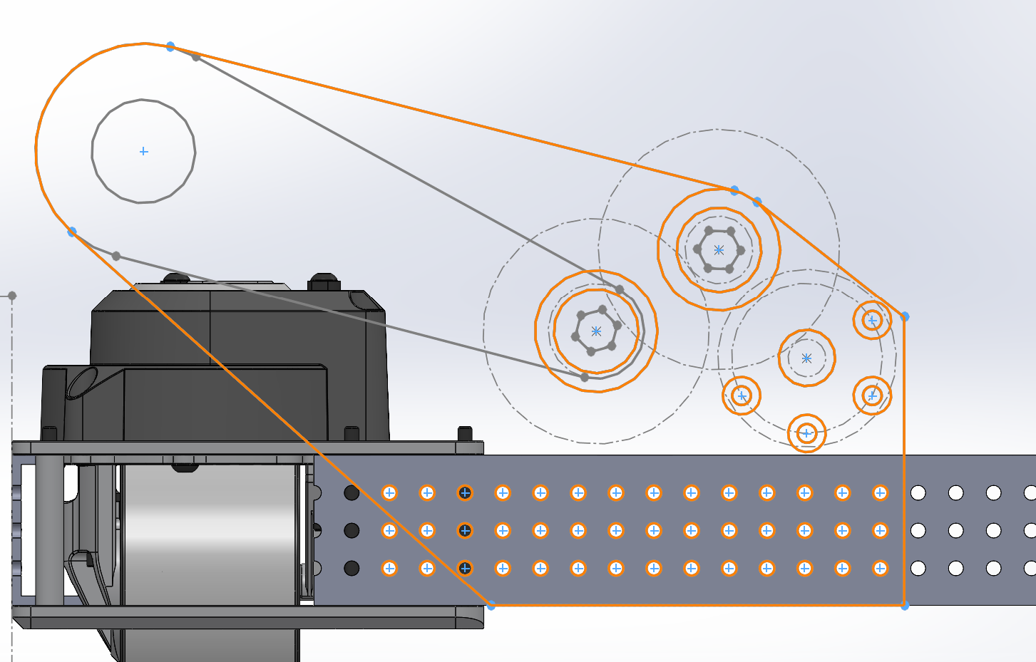
I started by making a powersketch of the gearbox and rollers. Taking inspiration from Team 1778’s 2025 intake, I suspended the gearbox over the box beam of the drivetrain to keep it from interfering with other components.
The chain is then connected to a Spline XL sprocket. I used a spline profile axle as my pivot since it is robust and its unique shape would prevent the sprocket from rotating independently of the shaft. This sprocket has a spline-shaped center allowing for it to be attached directly to the Spline XL shaft.
For the rollers, I didn’t measure out compression and just put them in adjustable positions.
The initial design looked like this:
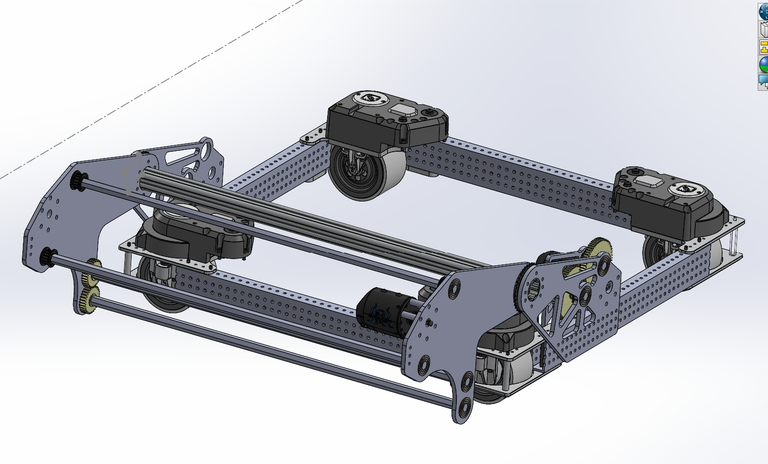
2. CAD Review and Initial Revisions
I communicated back and forth with my captain and had him do a CAD review for me, helping me figure out what needed to be changed.
The list included:
Accounting for the turnbuckle (which I had not known about prior)
Adding more pocketing to the outer gear plate
Increasing the size of the Spline XL sprocket
Adding compression
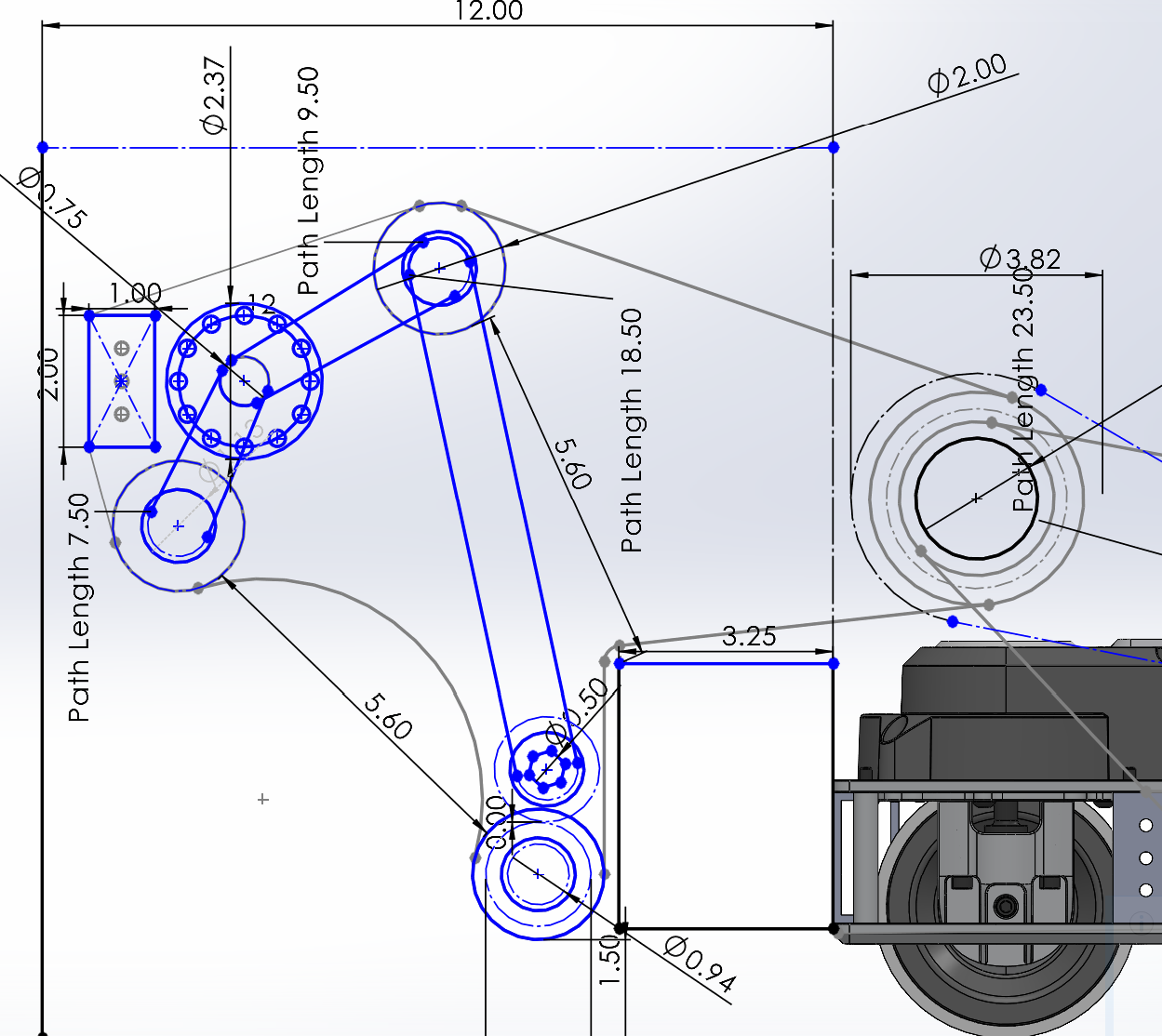
I changed the sprocket size from 36 teeth to 48 teeth, allowing for more torque.
I was told to use a roller spacing of 5.6 inches, but I realized that the direction-changing axle was coming in the middle. The original configuration I had wasn’t working, so I ended up moving the direction-changing axle up and out of the way.
3. Hopper Integration and Design Challenges
I was decently satisfied with this version, but more problems arose when I began working on the hopper plates.
I was taking inspiration from Teams 118 and 1678 for it, but thought that 1678’s design would be too difficult to make.
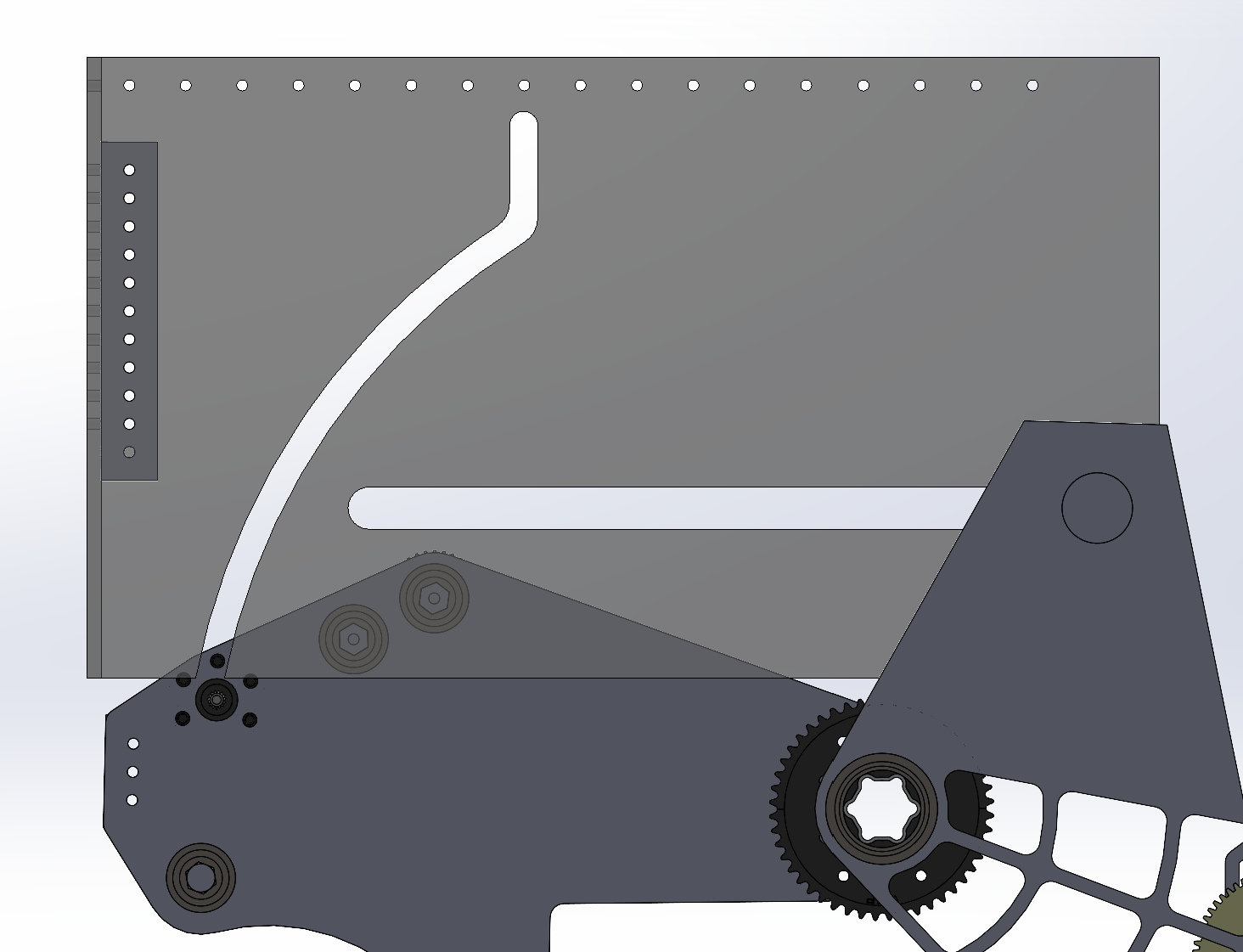
The idea was that a roller on the motor would slide along the slot in the plate. The curved part is concentric with the pivot so it doesn’t move the hopper until it reaches the straight part, allowing for agitation of the game pieces inside.
The problems with this were that:
There wasn’t enough support for the hopper plates since the sliding part would go completely out of the slot.
If anything were to hit the hopper and mess up the alignment, the intake would never be able to come up during a round.
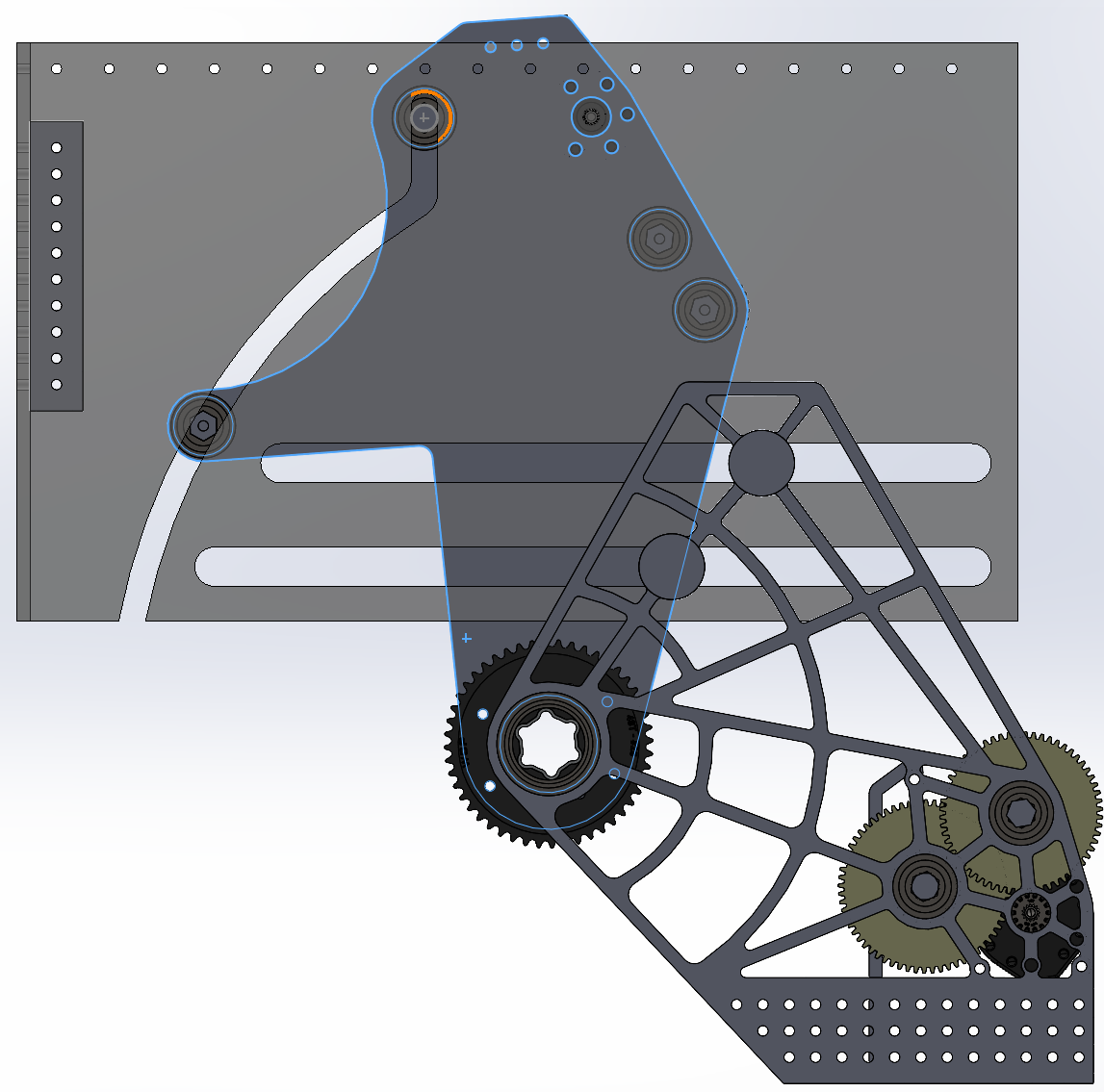
Aside from the support and practicality, the intake itself was too big and was going way above the plates. This meant that it would collide and potentially get caught in the net above.
With all of these issues combined, I went back to the sketch and began iterating more.
4. Revised Compression and Hopper Mechanism
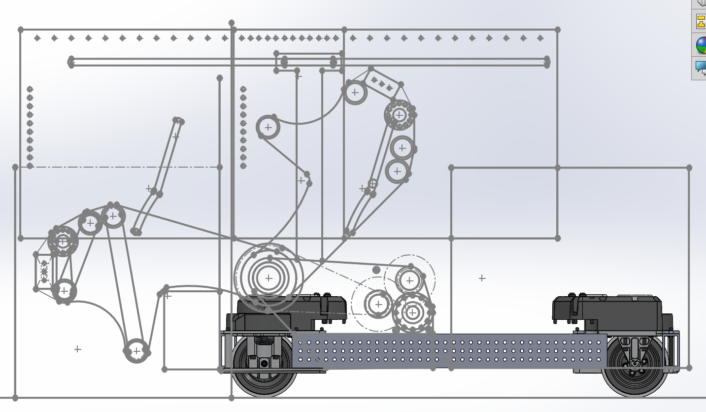
I ended up with the above sketch.
The main change I made was increasing compression; the maximum distance between the rollers was reduced to 5.2 inches. This allowed the intake to be much more compressed and reduced its length, allowing it to move up and down without any collisions in the revised CAD design.
Furthermore, I added a new slot such that its roller will always stay inside of it, allowing for much more support. A small portion is concentric with the pivot for agitation, while the rest is at an angle, similar to 1678’s.
I also extended the outer gear plate to provide more support for the hopper plates.
I was originally hesitant to try 1678’s mounting method but discovered that by setting a constraint to keep the roller centered in the slot, you can model the movement in the sketch itself.
This proved to be very beneficial as I was able to account for collisions before discovering them in the assembly.
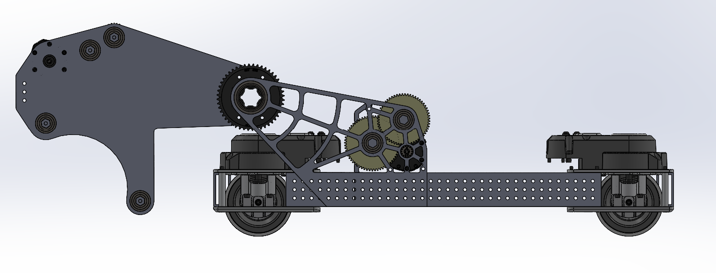
5. Final CAD Assembly
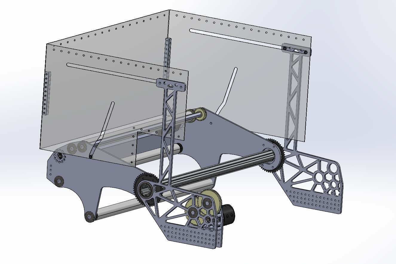
This was my final CAD assembly.
I took a chunk out of one of the hopper plates since it was colliding with the turret tower on the bot. I added holes around that area to provide space for a net to make up for the empty space.
I also changed the pocketing on the outer gear plate to have more triangles for better support.
CAD Challenges and How I Overcame Them
1. Component Collisions and Clearances
I encountered multiple challenges, especially when it came to avoiding collisions between components.
I had to account for chain width and outer diameters of the gears and pulleys, so I added the outer diameters of all the gears to my CAD model.
I adjusted spacer widths on multiple occasions to make sure the chain and turnbuckle wouldn’t hit anything.
Looking back, it would have been better to create a top-view sketch so I could see that perspective in the sketch itself.
2. SolidWorks Assembly Mates
Additionally, the program I was using, SolidWorks, repeatedly broke my assembly mates unexpectedly, which was really frustrating.
Upon some research, I discovered an auto-repair function which helped out a lot since I didn’t have to redo mates each time.
3. Length and Height Constraints
I also had a very difficult time keeping everything inside the length and height constraints.
To overcome this, I created reference lines in my sketch and made sure everything was inside them. This helped me stay within the required limits.
This reinforced how important a good sketch is.
Assembly and Integration Challenges
Unfortunately, the design did not work once we finished assembly. There were several problems, including the intake hitting the bumpers during deployment, the hopper hitting the intake bolts when being deployed, and a chain collision in the gearbox.
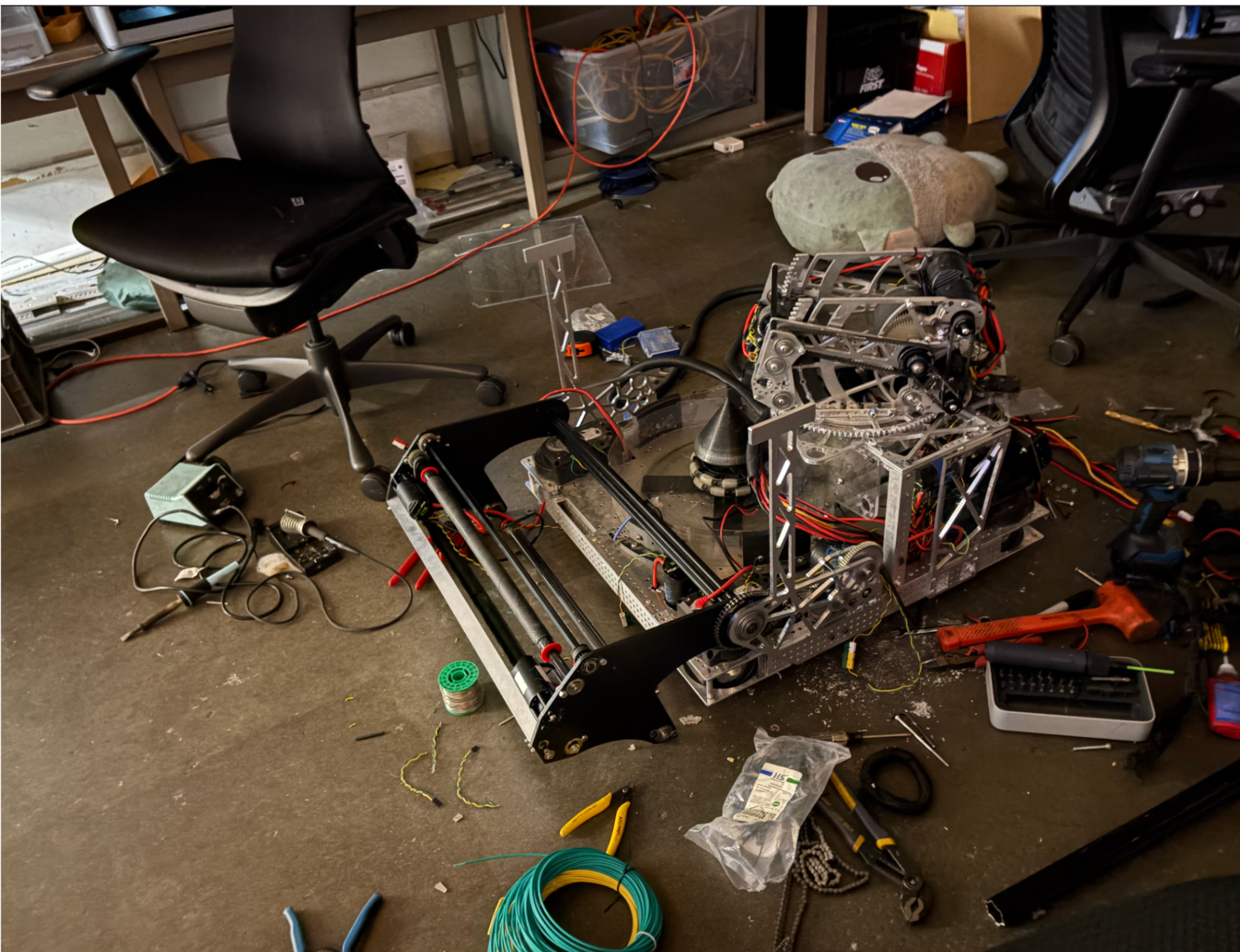
1. Component Collisions
In the future, I would definitely account for bolts in the CAD since, while they are very small, they can make a big difference when it comes to assembly.
Bumpers were not included in our CAD, which made it difficult to see how they would interact with the intake.
2. Component Availability
We also had to scramble to find certain components last minute, which resulted in small changes having to be made in the gearbox.
Additionally, taking inventory of what the team has is very important. I assumed we would have 18-tooth gears, but it turns out we didn’t.
3. Communication and Project Timeline
I do think that since this was designed over the summer, limited interaction with my team resulted in important details, like bumper dimensions, being lost in translation.
Thorough communication is essential, especially in a big project like this.
We also began the assembly a lot later than we should have, which meant there was not enough time to iterate once the design was built.
4. Lessons Learned
While it didn’t work in the end, designing it was an extremely valuable learning opportunity I am glad I took.
Going forward, I’ll be paying more attention to things like bolt widths, available materials, and possible collisions. I’ll make a top-view sketch as well in order to better see how components are interacting from a different perspective, and I’ll engage in thorough communication with my team.
Reflection
This was the first time I ever designed an entire mechanism independently, and while it was more difficult than anything I had designed before, it was also much more rewarding.
I learned a lot, from important mechanical design considerations such as chain tensioning to new SolidWorks tools like auto-repair and cam mates (which I used to model the motion in the assembly). I’m also a lot more comfortable with pocketing.
One of my biggest takeaways was learning that making something work in CAD doesn't necessarily mean it will work once assembled. I realized how important it is to account for every component, communicate with the rest of the team throughout the design process, and leave enough time for physical testing and iteration.
Overall, being able to design and assemble the mechanism has helped me better understand how the different components work together and given me much more confidence and experience with CAD.
Although the intake ultimately wasn't used in competition, I'm glad I took on the challenge of designing it myself. I’ve learned a lot and gained a lot of confidence in CAD as well, but there are miles to go before I sleep.