Gearbox Design
This project explores the design of a two-stage spur gearbox intended for use in FRC-style robotics. It focuses on understanding gear ratios, packaging constraints, and component interference through CAD-based iteration.
Project Overview
A gearbox allows for more or less torque via one or more stages of gear ratios. This is a vital part of FRC mechanisms as many require heavy loads to be moved, requiring much higher torque than the motor alone can provide. Though it plays such an important role, a gearbox is not a super complex mechanism, and thus was an ideal choice for an introduction to CADing in FRC.
How it Works
By connecting multiple gear stages together, the gear ratios of each stage multiply to create a larger one, resulting in a compact system that efficiently adjusts torque.
A more in-depth explanation of this system is as follows:
Design Constraints
Gearboxes should be compact and as small and lightweight as possible in order to avoid interfering with other mechanisms and adding unnecessary weight to the robot. This is most easily done by keeping the pinion as small as possible to keep the next gear small as well, but doing this can result in collisions and often one will be unable to achieve as compact a gearbox as they’d like.
Design Process
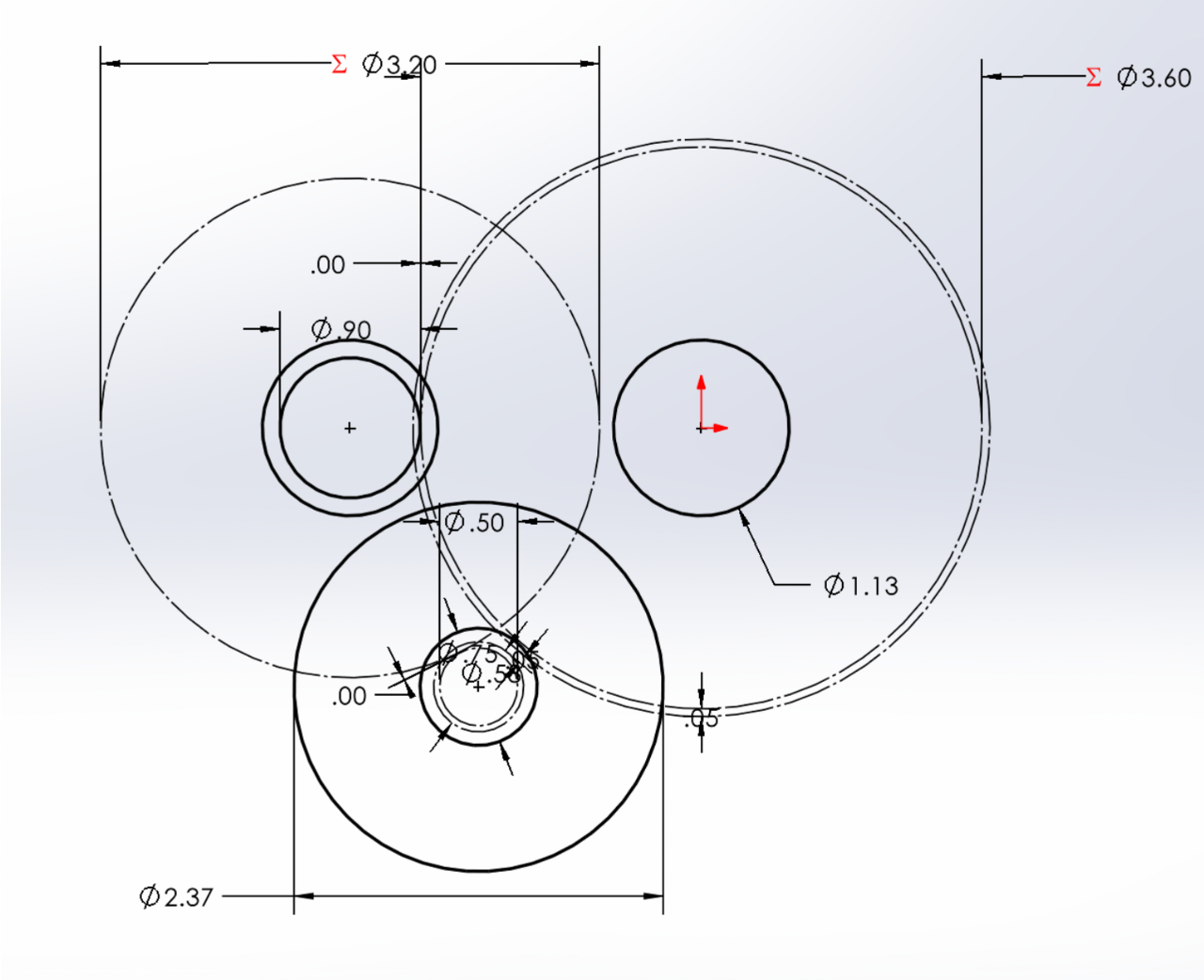
The first step is designing the plate that supports the gears (includes attachments for motor, bearings, standoffs). To do this, I first made a sketch, displaying all the important components of the gearbox.
Our standard motor is a Kraken X60; this motor is mounted on the plate and has a diameter of 2.367 inches. The part housing the motor’s bearing has a diameter of .75 inches, and this hole is cut into the plate. For a two stage gearbox such as this one, there will be two axles and each needs its own bearing. The bearings used have an inner diameter of 1.125 + .002 inches for tolerance, and a hole of this size is also cut into the plate.
To model the meshing of each gear stage, I set the distance between each gear’s pitch diameter .002 inches apart for tolerance.
To keep the gearbox as compact as possible, I started with the smallest pinion available, which is 8 teeth. For a 2 stage gearbox, the end ratio is the product of the individual ratios on each stage. By keeping the pinion as small as possible, you can get a higher ratio on the first stage while keeping the second gear relatively small.
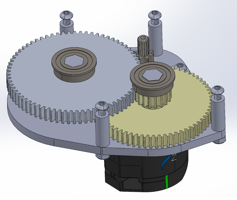
The first gear of the second stage is 18 teeth and engages with a 72 tooth gear; a ratio of 4:1. This means the total gear ratio of 32:1, providing very high torque.
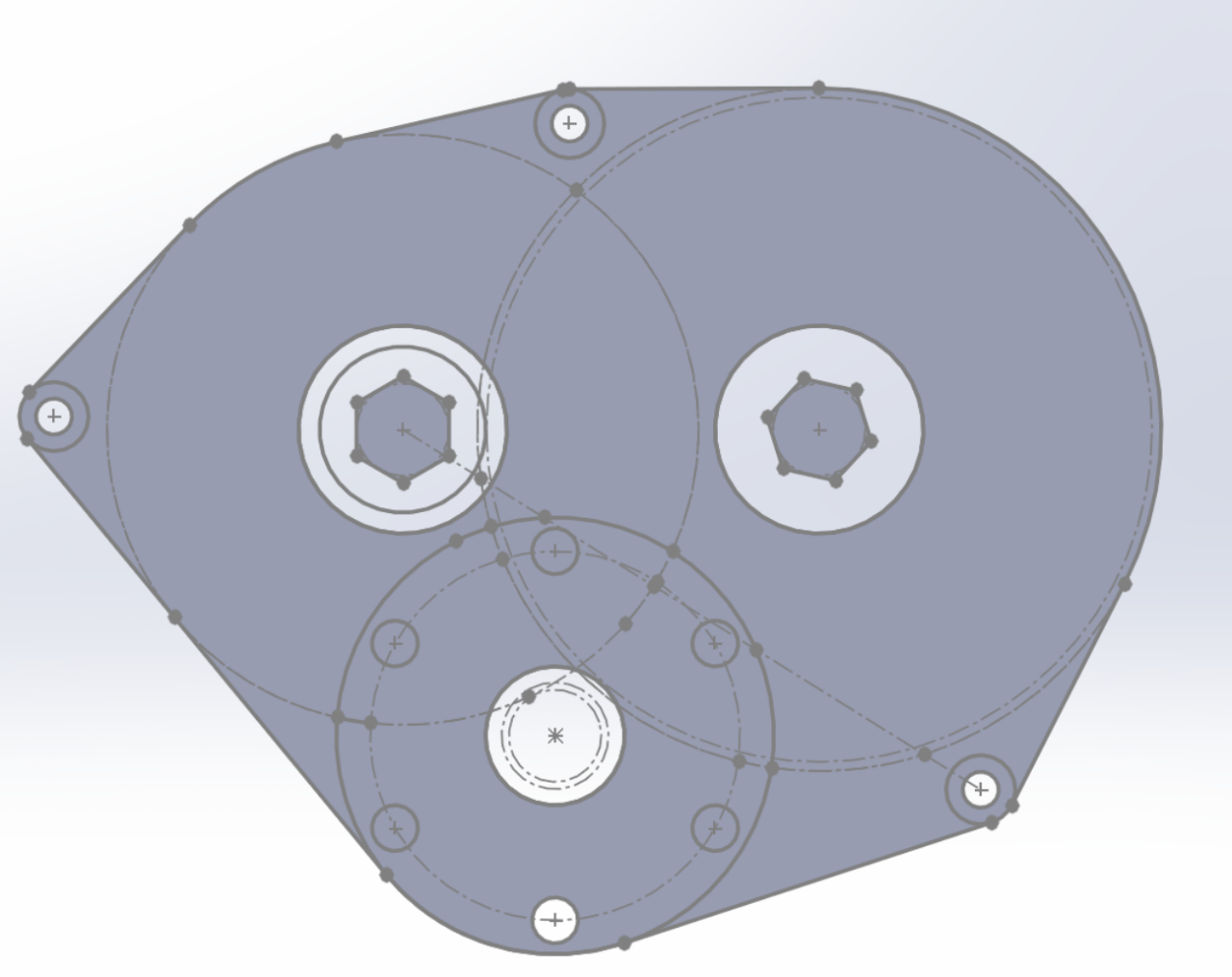
The material used for the plate is ¼ aluminum sheet metal, so the plate is extruded to a depth of ¼ inch.
Though the gears are arranged in a triangular structure in the picture, originally everything was sketched in a line. A line of gears takes up far more space than this condensed, triangle formation. Once the sketch is completed, tangent lines are drawn in to create the frame of the plate, as well as holes to mount the motor and place standoffs between the two plates sandwiching the gears.
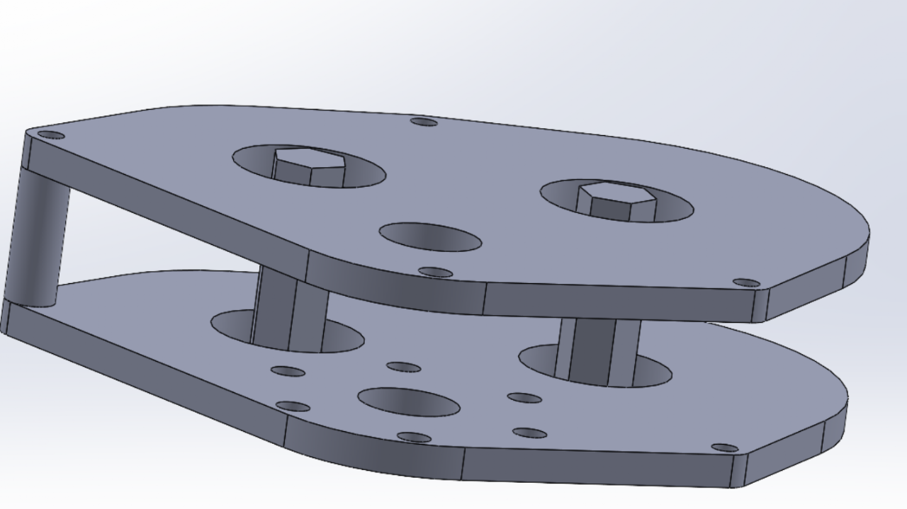
Each gear is .5 inches in width, so for two stages there should be an inch between the two plates. I duplicated the plate in the same part on solidworks to simplify the assembly using the linear pattern tool to space them appropriately. Though, I did leave out the holes for mounting the motor on the second plate as those holes would never be used; the remaining one is for a standoff. Along with the plates, ½ inch hex axles and standoffs are also created. The axles span the length of the plates while the standoffs keep the plates spaced apart appropriately.
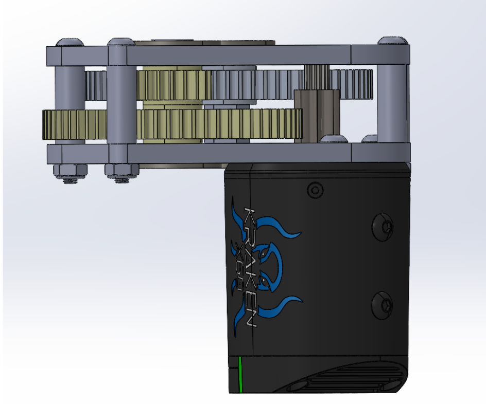
After this, the assembly is relatively straightforward. Each component is imported from WCP (West Coast Products; a standard FRC supplier) and mated to the correct position, appearing as follows.
Challenges
While I accounted for the bearing hole, I originally neglected the flange while making the sketch. This resulted in collisions between the motor and bearing which I didn’t notice until I got to the assembly. I had to adjust the gear ratio to avoid it, which was an unnecessary hassle that could have been easily avoided had I accounted for the flange originally. I definitely won’t be making this mistake again.
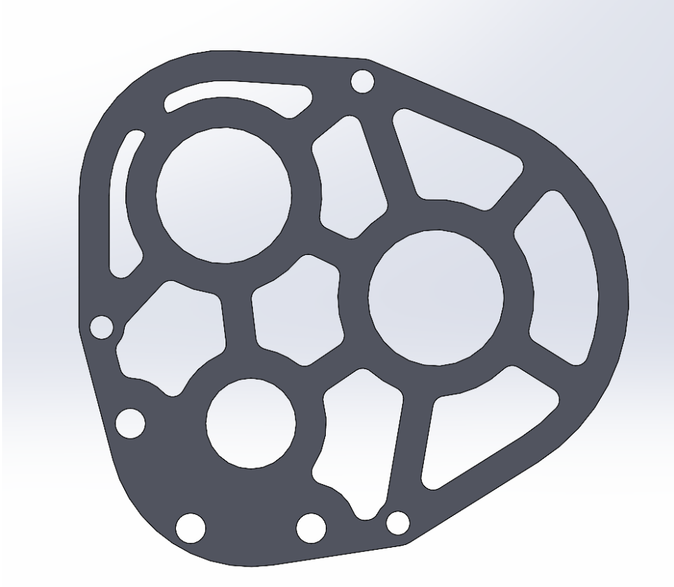
Additionally, since this was the first time I had assembled a gearbox, I didn’t window my plates. Windowing is a simple method that cuts large openings in the plate, reducing the weight of the metal used. While I didn’t do that on this gearbox, I later made other gearboxes where I did. A ¼ inch frame around the perimeter and holes of the plate is kept, and ¼ inch lines are drawn between them. When extruding, those cut outs are kept open, creating a supported structure which is much lighter than an entire plate.
Reflection
This project was a good practice for an important part of FRC robots. Having to be aware of issues like the collisions, figuring out how to efficiently mate things in solidworks (using tools such as copy with mates), and seeing how the components interact in 3d was a really good learning experience and gave me the confidence to take on more complex CAD projects in the future.
Glossary
- Bearing: Allows for smooth rotational movement
- Standoff: Spacer to hold to parts at a fixed distance
- Stage: A pair of meshed gears
- Pinion: a small gear that goes directly on the motor shaft
- Tolerance: Added distance to account for small discrepancies in the dimensions of the machined part
- Pitch Diameter: # of teeth/DP; the diameter of the gear where its teeth will mesh with other teeth
- Diametrical Pitch (DP): the value of teeth per inch of the gear’s pitch diameter. This value is 20 for pretty much all gears, though pinions are a special case
- Torque: amount of applied force; more torque means being able to lift heavier loads.